80
MAY2016
FOOD FOCUSTHAILAND
SOURCE OF
ENGINEER
• The choice of materials to suit operating conditions:
The materials used in equipment surfaces that come in
contact with food products should be corrosion resistant,
easy toclean,heat resistant,non-toxic,andnon-absorbant.
Stainless steels (AISI series 300 or better) are commonly
used in theprimarystructuresof food-productionequipment.
Polymericmaterialsareused forpreventingdirectmetal to
metalcontactofpartsowing topolymers’corrosion-resistant
properties. Elastomers are generally used as gaskets or
seals which must be appropriately selected to prevent
expansion or deformation during operations. The surface
in contact with the food product should have an average
roughness of less than or equal to 0.8microns (R
a
< 0.8
µm), and theequipment surfaceshouldnot bepainteddue
to thepotential for product contamination.
• Designing equipment to avoid crevices and dead
areas or shadow zones: Crevices and dead areas can
trap product residue, cleaning agents, and disinfectants.
Pumpandvalvedesignmust ensure that noair gapexists
when liquids flows. Also, parts with sharp edges should
be avoided, and anglesmust be less than or equal to 90
degrees.Valvesmust avoidusing threads. If adeadspace
cannot be avoided, it should be designed to be as short
distance as possible and positioned to easily drain liquids
andallow for easy cleaning.
• Installingequipmenton theproduction line: Itmustbe
ascertained for certain that theequipment designdoesnot
impede cleaning-in-place (CIP) or draining of liquids, and
this includesequipmentpartswhichareconnected together.
Itmustalsobedetermined thatno leakageorcontamination
of products withmicroorganisms is occurring by regularly
checking the possible deteriorationof elastomer seals.
• Installation of pipe systems shouldallow space
betweenpipes to reduceheat transferand forease
of cleaning.
• Installinghorizontal pipesshould take intoaccount
their ability to drain liquids by providinga slopeof
3degrees in thedrainage area.
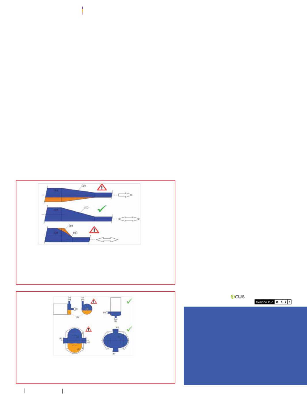
• When connecting horizontal pipeswithdifferent
diameters, it is preferable to reduce thepipe sizes
witheccentric reducersso that theircentersarenot
aligned (Figure1).
• Pump installationmust ensure that thepump is in
apositionwhichallows for thecompletedrainingof
liquid (Figure 2).
หรื
อซี
ล ซึ่
งต้
องเลื
อกใช้
ให้
เหมาะสม เพื่
อป้
องกั
นไม่
ให้
เกิ
ดการขยายตั
วหรื
อเสี
ยรู
ปในสภาวะการใช้
งาน
โดยพื้
นผิ
วที่
สั
มผั
สกั
บผลิ
ตภั
ณฑ์
ควรมี
ค่
าความขรุ
ขระเฉลี่
ยน้
อยกว่
าหรื
อเท่
ากั
บ 0.8 ไมโครเมตร
(R
a
<0.8µm) และไม่
ควรทาสี
ที่
พื้
นผิ
วของอุ
ปกรณ์
เนื่
องจากอาจเกิ
ดการปนเปื้
อนไปยั
งผลิ
ตภั
ณฑ์
ได้
• การออกแบบโดยหลี
กเลี่
ยงการเกิ
ดร่
องรอยแตก (Crevices) และพื้
นที่
อั
บ (Dead area or
Shadowarea) ซึ่
งจะท�
ำให้
เกิ
ดการขั
งนิ่
งของผลิ
ตภั
ณฑ์
สารท�
ำความสะอาดและสารฆ่
าเชื้
อ โดยการ-
ออกแบบปั
๊
มและวาล์
วต้
องมั่
นใจว่
าไม่
มี
ช่
องอากาศอยู
่
เมื่
อของเหลวไหลผ่
านและหลี
กเลี่
ยงชิ้
นส่
วนที่
มี
ขอบคมและมุ
มแหลมที่
น้
อยกว่
าหรื
อเท่
ากั
บ 90 องศา บริ
เวณวาล์
วต้
องไม่
มี
เกลี
ยว และถ้
าไม่
สามารถ
หลี
กเลี่
ยงพื้
นที่
อั
บได้
ควรออกแบบให้
พื้
นที่
อั
บมี
ขนาดสั้
นที่
สุ
ดเท่
าที่
จะเป็
นไปได้
และอยู
่
ในต�
ำแหน่
ง
ที่
สามารถระบายของเหลวและท�
ำความสะอาดได้
• การติ
ดตั้
งอุ
ปกรณ์
ในสายการผลิ
ต เพื่
อให้
แน่
ใจว่
าอุ
ปกรณ์
ไม่
ขวางการท�
ำความสะอาดแบบ CIP
(Cleaning inplace)และสามารถระบายของเหลวออกได้
(Draining)รวมถึ
งการต่
ออุ
ปกรณ์
(Joining)
ต้
องมั่
นใจได้
ว่
าไม่
เกิ
ดการรั่
วหรื
อการปนเปื
้
อนของผลิ
ตภั
ณฑ์
กั
บจุ
ลิ
นทรี
ย์
ด้
วยการหมั่
นตรวจสอบ
การเสื่
อมสภาพของวั
สดุ
อิ
ลาสโตเมอร์
ที่
ท�
ำหน้
าที่
เป็
นซี
ลกั
นรั่
ว
• การติ
ดตั้
งระบบท่
อควรมี
ช่
องว่
างระหว่
างท่
อเพื่
อลดการถ่
ายเทความร้
อนและง่
ายต่
อการท�
ำความ-
สะอาด
• การติ
ดตั้
งท่
อในแนวนอนควรค�
ำนึ
งถึ
งความสามารถในการระบายของเหลวได้
โดยควรมี
ความ-
ชั
นลาดเอี
ยง 3องศาที่
บริ
เวณจุ
ดระบายทิ้
ง
• การเชื
่
อมต่
อท่
อที่
วางตั
วในแนวนอนและมี
ขนาดเส้
นผ่
านศู
นย์
กลางแตกต่
างกั
น นิ
ยมลด
ขนาดท่
อแบบจุ
ดศู
นย์
กลางไม่
ตรงกั
น (รู
ปที่
1)
• การติ
ดตั้
งปั๊
มต้
องมั่
นใจว่
าปั๊
มติ
ดตั้
งในต�
ำแหน่
งที่
สามารถระบายของเหลวออกได้
หมด (รู
ปที่
2)
เอกสารอ้
างอิ
ง/References
การรั
บรองมาตรฐานของ EHEDG
_
Recertification_2014.pdf]
EHEDGGuidelineNo. 8: Hygienicequipment designcriteria, 2
nd
edition, 2004
EHEDGGuidelineNo.10:Hygienicdesignofclosedequipment for the
processingof liquid food
EHEDGGuidelineNo. 14: HygienicRequirements of valves for food
processing
EHEDGGuidelineNo. 17: HygienicRequirements of valves for food
processing
Holah, J. andLelieveld, L.M. 2011.Hygienicdesignof food factories,
WoodhedPublishingLimited.
ข้
อมู
ลเพิ่
มเติ
ม/Additional Information
Readmoreabout “HygienicEngineeringandDesign” at
. And follow the
EHEDG. ThailandFanpage:
.
รู
ปที่
2
Centrifugal pump (บน) และ Lobepump (ล่
าง) [EHEDGGuidelineNo.10]
Figure 2
Centrifugal pump (above) and Lobe pump (below) [EHEDGGuidelineNo.10]
(a) บริ
เวณผลิ
ตภั
ณฑ์
(b) การลดขนาดแบบจุ
ดศู
นย์
กลางตรงกั
น (c) การลดขนาดแบบเยื้
องศู
นย์
แบบท่
อยาว
(d) การลดขนาดแบบเยื้
องศู
นย์
แบบท่
อสั้
น (e) พื้
นที่
จุ
ดอั
บที่
เกิ
ดขึ้
นได้
(a) product area (b) concentric reducer (c) eccentric reducer, long version
(d) eccentric reducer, short version
(e) potential shadow zone
(a) พื้
นที่
ผลิ
ตภั
ณฑ์
(b) ทางเข้
า (c) ทางออก (d) ส่
วนที่
ไม่
สามารถระบายของเหลวออกได้
(a) Product area (b) Inlet (c) Outlet (d) Undrainable volume
รู
ปที่
1
การลดขนาดท่
อ [EHEDGGuidelineNo.10]
Figure 1
Transition of pipediameters [EHEDGGuidelineNo.10]


